How Fluid Couplings Work

Fixed-fill, delay-chamber and variable-speed couplings explained

Fluid couplings are mechanical devices fitted between a motor or engine and a driven machine. They are commonly used on equipment such as conveyors, crushers, mills, fans, pumps and propeller-driven systems.

The original concept of the fluid coupling was conceived by Hermann Föttinger. Over time, this principle developed into the wide range of modern fluid coupling designs used throughout industry.

A primary function of a fluid coupling is to provide the motor with a virtually no-load starting condition, allowing the driven machine to be accelerated progressively. The coupling also provides an important safety element within the drivetrain should an overload or failure occur elsewhere in the system.

Regardless of manufacturer or design, a fluid coupling fundamentally consists of four elements:

  1. Impeller: connected to the driving machine
  2. Runner: connected to the driven machine
  3. Working fluid: transmits torque through hydrodynamic action
  4. Casing: surrounds the impeller and runner and contains the working fluid

There is no physical mechanical connection between the impeller and runner. Power is transmitted by the movement of the working fluid. The basic power path can therefore be represented as:

Motor or engine → Impeller → Working fluid → Runner → Driven machine
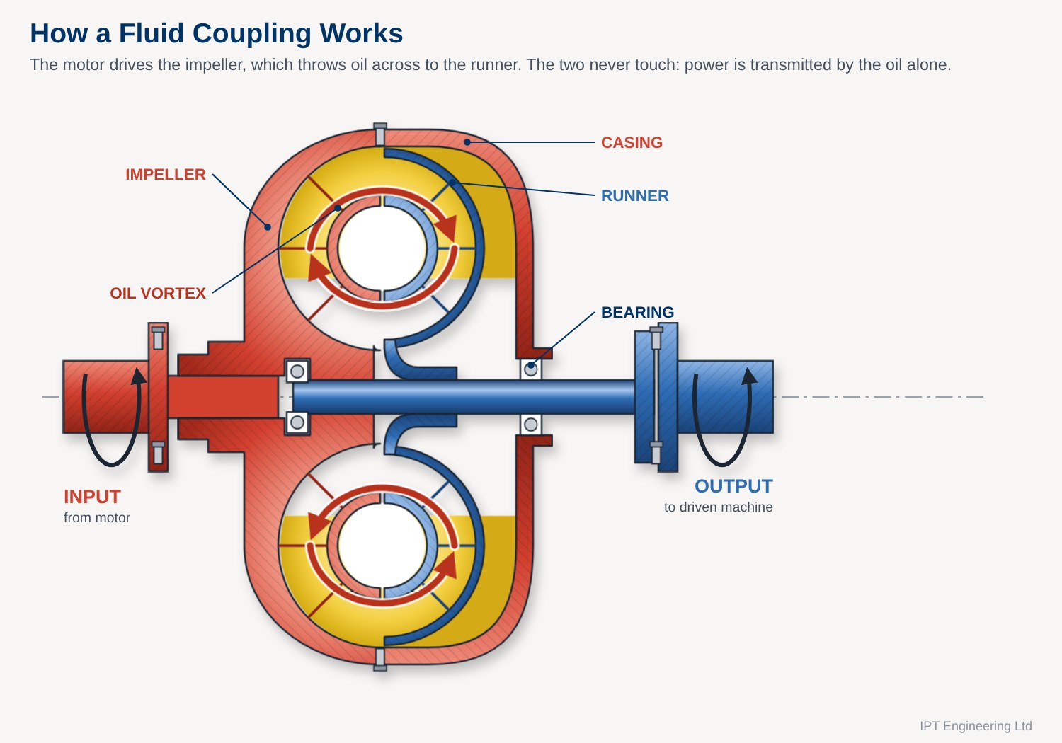
Section through a fixed-fill fluid coupling showing the impeller, runner, casing and oil vortex
Fixed-fill fluid coupling: the impeller throws oil across to the runner; the circulating oil vortex carries the power

Fluid couplings can broadly be divided into two categories: fixed-fill couplings and variable-speed couplings.
Fixed-Fill Fluid Couplings

Soft starting from a squirrel-cage motor

A fixed-fill coupling contains a predetermined quantity of working oil.

On starting the motor, the coupling provides a near no-load condition on the motor before progressively accelerating the driven load to full speed. Fixed-fill couplings make use of the inherent characteristics of a squirrel-cage induction motor to accelerate the load.

Once the driven machine reaches operating speed, the coupling transmits sufficient power from the motor to drive both itself and the driven load.

A correctly sized fixed-fill coupling will typically operate with approximately 3–5% slip under normal operating conditions.

Slip and Overload Protection

The safety characteristic of a fixed-fill fluid coupling is not simply torque limitation. Its important protective characteristic is the increase in slip between the impeller and runner when the driven machine becomes overloaded.

Under normal operating conditions, the runner rotates only slightly slower than the impeller, resulting in relatively low slip.

If the driven machine becomes overloaded, the runner slows down. This increases the slip between the impeller and runner, with a corresponding increase in energy being converted into heat within the working fluid.

In a stall condition, the runner may stop while the impeller continues to rotate. Slip can therefore approach 100%, resulting in rapid heat generation within the coupling.

Prolonged operation under these conditions can result in excessive working-fluid temperatures and potential damage to the coupling, seals and working fluid. Thermal protection, such as a fusible plug, is therefore an important consideration in applications where prolonged overload or stall conditions are possible.

When to Use a Fixed-Fill Coupling

Fixed-fill couplings are generally suitable for applications that do not require speed control but where the motor needs:

This makes fixed-fill couplings particularly useful on installations where the available electrical supply is relatively weak.

Delay-Chamber Fixed-Fill Couplings

A longer, gentler start for long conveyors

A variation of the fixed-fill coupling incorporates a delay chamber.

At rest, these couplings retain a proportion of the working-circuit oil in an extended outer casing or delay chamber.

On start-up, the oil retained in the external chamber is thrown towards the outside of the casing by centrifugal force and feeds into the working circuit through nozzles.

These couplings provide an extended start-up period and can limit the transmitted torque to around 140% of full-load motor torque during acceleration. The result is a long, progressive acceleration characteristic.

This makes delay-chamber couplings particularly effective on long conveyor belts, where they help prevent excessive tensions from being generated during starting. This can minimise wear on conveyor joints and reduce belt slap.

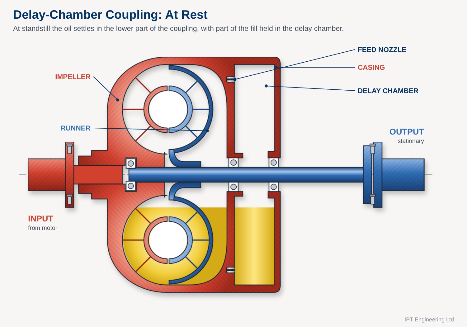
Delay-chamber fluid coupling at rest with oil settled in the lower part of the coupling and delay chamber
At rest: part of the oil fill is held in the delay chamber
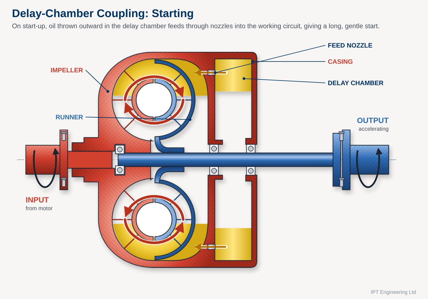
Delay-chamber fluid coupling starting, with oil feeding through nozzles from the delay chamber into the working circuit
Starting: oil feeds through the nozzles into the working circuit

Variable-Speed Fluid Couplings

Speed control from a fixed-speed motor

Variable-speed fluid couplings fall into two principal categories: scoop-filling couplings and scoop-trimming couplings.

Both designs use scoop tubes to control the quantity of oil contained within the working circuit. These types of coupling are suitable for applications requiring variable-speed control while using a fixed-speed motor.

The stable speed reduction that can generally be achieved depends on the type of driven load:

Scoop-Filling Couplings

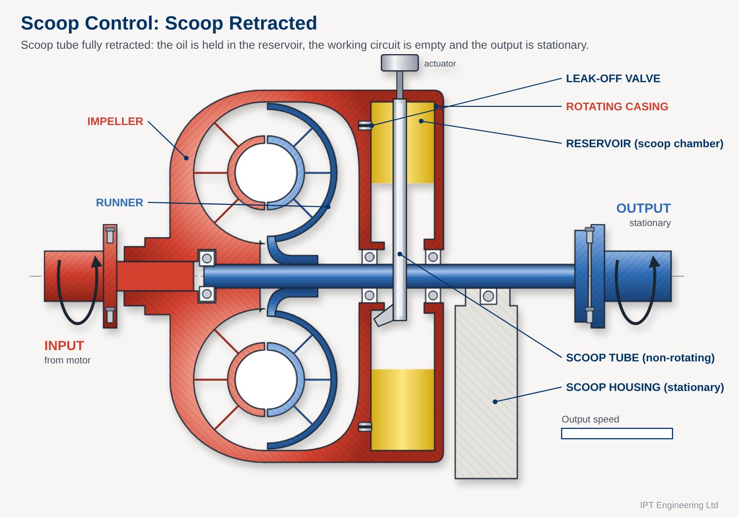
A scoop-filling coupling typically has its working circuit located within a reservoir. The reservoir is connected to and rotates with the motor and impeller.

When the coupling is at rest, the working fluid is contained within the reservoir and the working circuit is effectively empty.

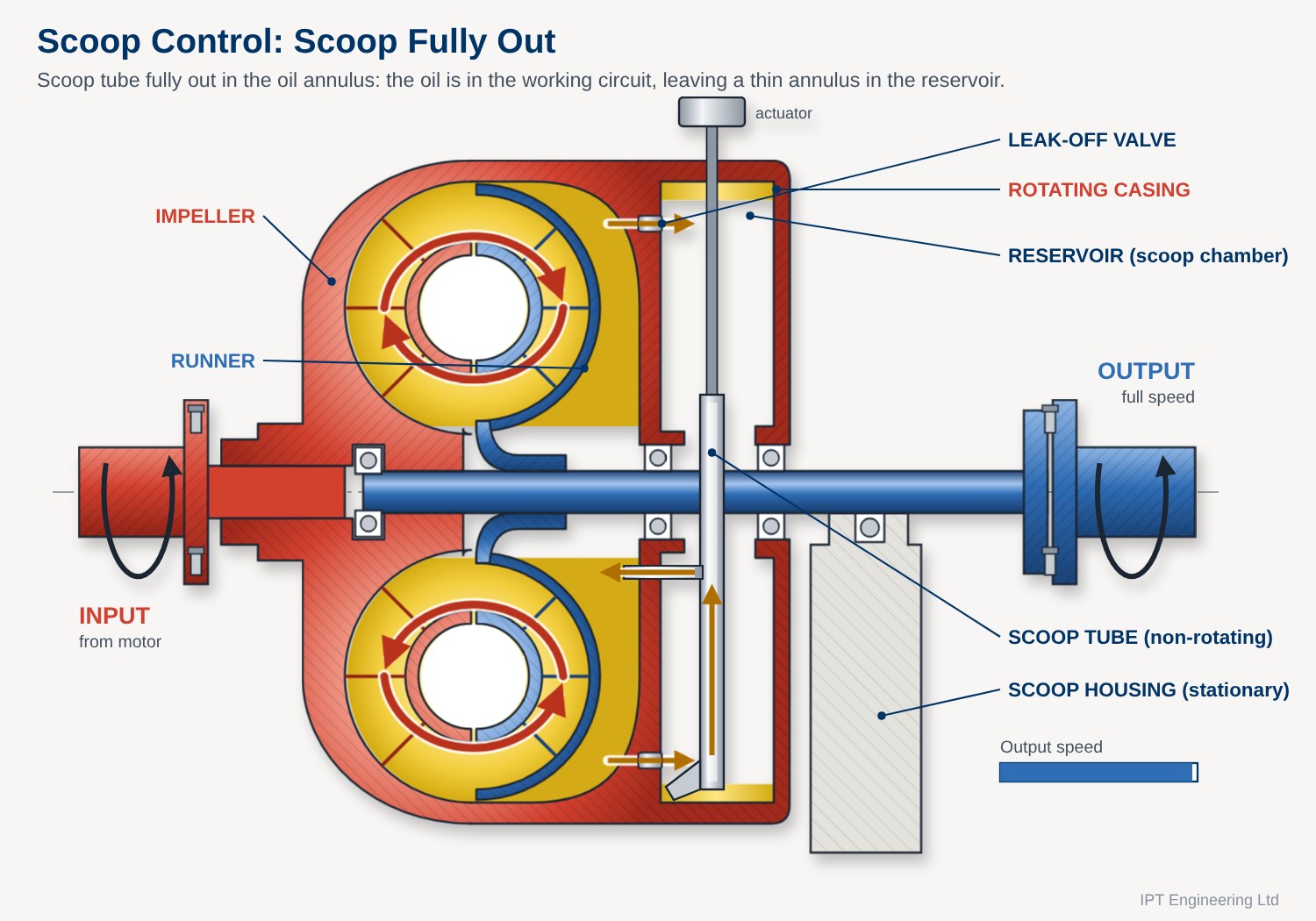
When the motor starts, the reservoir and impeller rotate at motor speed. Due to the rotational effect, the working fluid forms an annulus of oil against the inside wall of the reservoir, while the working circuit remains substantially empty.

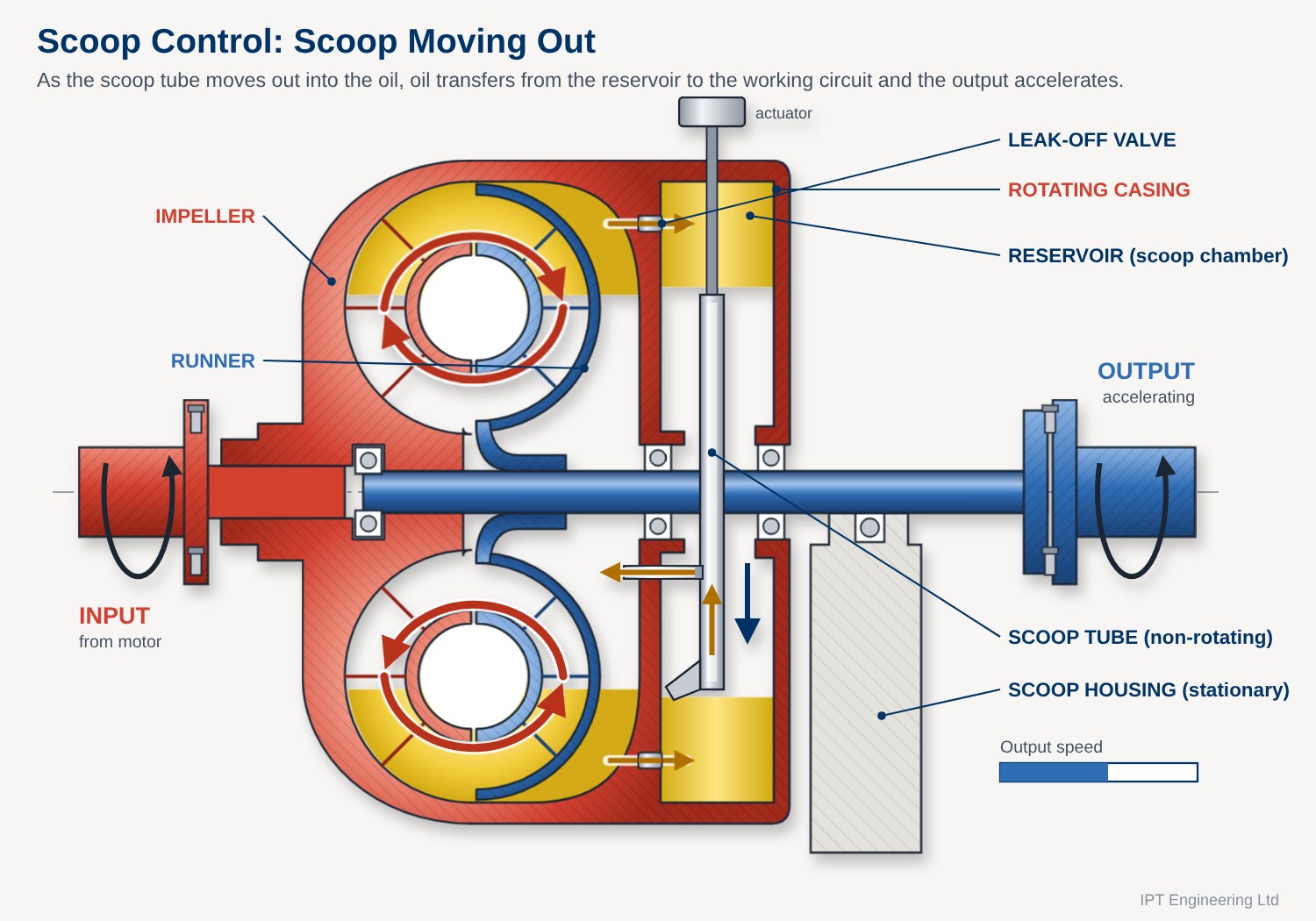
A scoop tube is extended into this annulus of oil by a control mechanism. The scoop tube collects the oil and transfers it into the working circuit.

As the scoop tube is extended further into the oil annulus, an increasing quantity of oil is transferred into the working circuit. This increases the amount of working fluid available to transmit torque and progressively accelerates the driven machine towards the required operating speed.

Scoop-filling fluid coupling with the scoop tube retracted, oil held in the reservoir and the working circuit empty
1. Scoop retracted: oil held in the reservoir, working circuit empty, output stationary
Scoop-filling fluid coupling with the scoop tube moving out and oil transferring into the working circuit
2. Scoop moving out: oil transfers to the working circuit and the output accelerates
Scoop-filling fluid coupling with the scoop tube fully out and the working circuit full
3. Scoop fully out: working circuit full, a thin annulus left in the reservoir, output at full speed

Working-Circuit Oil Control

Flow within the working circuit is controlled by valves located around the periphery of the coupling. These valves allow oil to leak from the working circuit back into the reservoir.

The balance between the rate at which oil enters the working circuit and the rate at which it returns to the reservoir controls the quantity of working fluid contained within the circuit. This provides continuous control of the coupling’s transmitted torque and therefore the speed of the driven machine.

The circulation of oil also provides a degree of cooling. As the coupling rotates, heat generated within the working fluid can be dissipated through the coupling casing and surrounding structure.

This combination of scoop-tube position, working-circuit oil volume and heat dissipation allows the scoop-filling coupling to provide controlled variable-speed operation from a fixed-speed motor.

Scoop-Trimming Couplings

High-power variable-speed drives

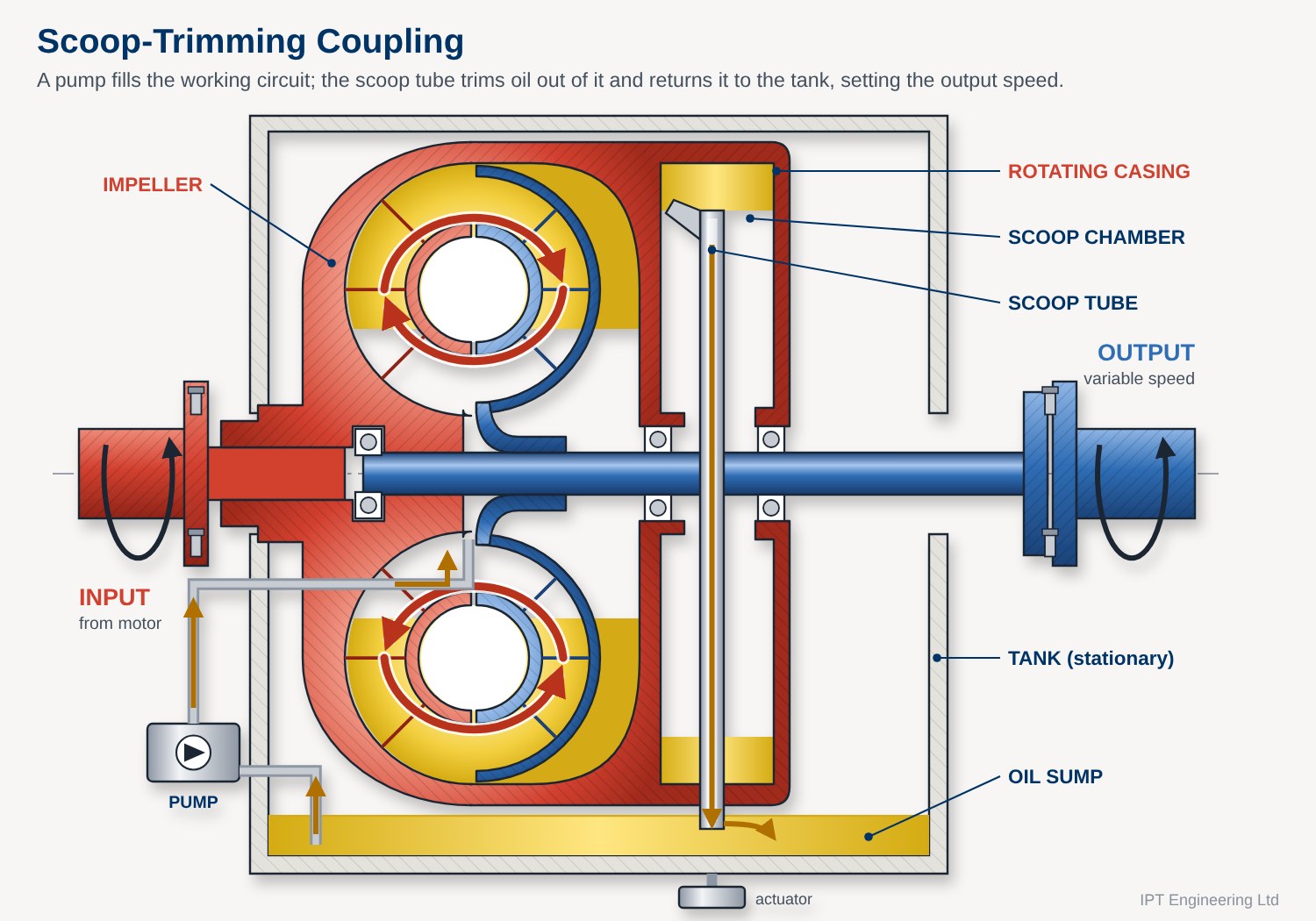
Scoop-trimming couplings also use a scoop tube to control the quantity of working fluid in the working circuit.

However, unlike a scoop-filling coupling, the scoop tube in this design controls the output speed by trimming fluid out of the working circuit rather than adding fluid to it.

The working circuit is filled by a pump. Depending on the coupling design, the pump may be:

Using both an input-driven pump and an external electric pump can provide increased oil flow during start-up. This can be particularly important where the coupling uses plain bearings rather than rolling-element bearings, as adequate oil flow may be required to provide lubrication during starting.

Scoop-trimming couplings tend to be large units designed for high-horsepower applications.

Scoop-trimming fluid coupling in its tank, with a pump filling the working circuit and the scoop tube returning oil to the sump
Scoop-trimming coupling: the pump fills the working circuit and the scoop tube trims oil out, returning it to the tank

The working circuit is contained within a tank which performs two important functions. It provides structural support for the rotating elements of the coupling and also acts as a sump for the working fluid.

During operation, the pump supplies oil to the working circuit. The scoop tube removes a controlled quantity of oil from the circuit, returning it to the surrounding tank.

By controlling the amount of oil retained in the working circuit, the coupling controls the torque transmitted and consequently the speed of the driven machine.

This arrangement allows large amounts of power to be controlled while using a fixed-speed motor, making scoop-trimming fluid couplings particularly suited to large industrial drives where variable-speed operation, controlled acceleration and high-power transmission are required.

Scoop-Tube Control and Applications

Scoop-Tube Control

With both scoop-filling and scoop-trimming couplings, the position of the scoop tube is controlled by an external actuation device. Depending on the coupling and application, the scoop tube may be actuated by:

This external control allows the quantity of working fluid in the circuit to be adjusted while the coupling is operating, providing control of the transmitted torque and output speed.

Applications for Scoop-Filling Couplings

Scoop-filling couplings are used across a wide range of industrial applications. Their ability to provide controlled acceleration and variable-speed operation makes them particularly suitable for long, heavy-duty conveyor systems where high horsepower and extended acceleration times are required. Other applications include:

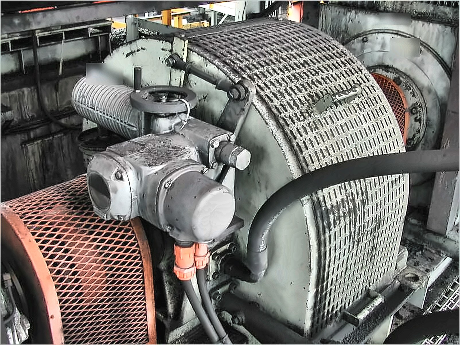
Scoop-controlled fluid coupling with electric scoop actuator on a double-drum coal conveyor drive
From our site experience: a scoop-controlled coupling with an electric scoop actuator on a double-drum drive coal conveyor

The ability to progressively introduce working fluid into the circuit allows acceleration to be controlled while limiting the stresses imposed on the driven equipment and associated mechanical components.

Applications for Scoop-Trimming Couplings

Scoop-trimming couplings are generally larger units, often constructed as substantial tank-type assemblies, and are particularly suited to high-horsepower applications. They are commonly used on:

Smaller scoop-trimming units can also be found on long conveyor systems, where their ability to control transmitted power and acceleration makes them suitable for demanding conveyor applications.

The combination of a fixed-speed motor with variable-speed control through the fluid coupling makes these systems particularly useful where the driven equipment requires controlled speed but a variable-speed electric motor is not the preferred solution.

Need Parts or Support for a Fluid Coupling?

IPT Engineering supplies spares and technical support for fixed-fill and scoop-controlled fluid couplings, including Fluidrive, Vulcan Sinclair, Pembril and SIME couplings. See our fluid coupling spares, fusible plugs, driving plates and output kits.

Send us the coupling type and size, or a photograph, and we will identify what you need. Send us the details or contact us.

All diagrams on this page are by IPT Engineering. Click any diagram to view it full size.